UNDERSTANDING SHAFT ALIGNMENT OPTIONS FOR CONVEYOR DRIVES
Shaft alignment takes on critical importance when you’re dealing with high horsepower motors. The least amount of angular misalignment or lateral displacement will lead to vibration, accelerated wear, and possibly even a catastrophic failure.
This is a particular issue with the heavy-duty conveyors used in mining, quarrying, and other aggregate transport applications. These conveyors carry heavy loads over long distances and may travel at high speeds. Misalignment between motor, gear reducer, and conveyor pulley can lead to costly downtime and could even pose a safety hazard.
Alignment-free drive systems are promoted as the solution to this problem. However, they’re not appropriate in every situation. Here’s a look at their strengths and weaknesses and a discussion of when a base mount drive might be the better choice.
BASICS OF HEAVY DUTY CONVEYOR DRIVE SYSTEMS
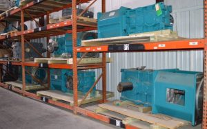
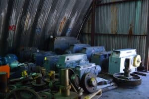
The three elements include a motor, a gearbox or speed reducer, and a coupling. The motor generates the rotation, the gearbox slows down the rotation while increasing the torque, and the coupling links the output of the gearbox to the conveyor pulley shaft.
Some points to note about these are:
- Motors are increasingly driven through variable frequency drives (VFDs.) A VFD provides more control over speed and more efficient operation.
- Gearboxes/reducers are produced in both right angle and parallel offset configurations.
- Heavy-duty conveyors often use fluid couplings as these reduce inertia and start-up loads.
- Motors, reducers, and fluid couplings need couplings to join their shafts to those of the other system components. These are either flanged couplings, taper bushings, or shrink disc designs.
ALIGNMENT-FREE OR BASE MOUNT: WHAT’S THE DIFFERENCE?
When the drive shaft is not precisely aligned with the pulley axis, forces acting on the pulley shaft will vary as the shafts turn. This causes vibration, rapid bearing wear, and can even shear the shafts, especially when the motor is generating high levels of power and torque.
One solution is to mount the motor and reducer on a solid base, typically a cast concrete pad, and very carefully align the axes with each other and with the pulley shaft. This is a time-consuming activity that needs precision measurement equipment and considerable skill.
The alternative is to mount the reducer directly to the pulley shaft, and the motor to the reducer, with the fluid coupling inserted at an appropriate location in the system.
This latter approach, mounting directly to the pulley shaft, is what’s called alignment-free. The point is that no alignment is required because it’s provided by the shafts.
ALIGNMENT-FREE DRIVE CONFIGURATION
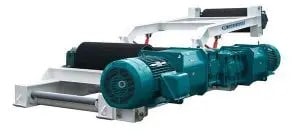
An alignment-free drive system almost always uses a right-angled reducer. This puts the motor alongside the conveyor rather than having it sticking out some distance from the belt.
A downside of the alignment-free configuration is that the reducer and motor are suspended from the pulley shaft. Consequently, a suspended load must be taken into account when sizing a pulley shaft appropriately. Additionally, a torque arm must be included in alignment-free drive systems to stop the drive assembly from rotating around the pulley shaft. A torque arm connects the reducer to the conveyor frame.
In some situations, this torque arm is rigidly mounted to the reducer and conveyor frame. More commonly though, there’s some compliance in the linkage to accommodate runout in the pulley shaft.
An important consideration when designing an alignment-free drive is to know if the motor will ever be reversed. If this is the case the torque will act in the opposite direction and most types of torque arm, such as a turnbuckle, will give way under the compressive load. To combat this, drives that will run in both directions will usually be fitted with two torque arms.
STRENGTHS OF ALIGNMENT-FREE DRIVES
- Misalignment problems are avoided, preventing rapid wear, fatigue, and even catastrophic failure
- Limited site work required before installation
- Simple to install
- Minimizes space needed for the drive (an especially attractive characteristic in confined places like underground mines).
- Minimal energy wasted in the drive transmission system (therefore very efficient)
- Used in both surface and underground conveyor applications
LIMITATIONS OF ALIGNMENT-FREE DRIVES
Alignment-free systems are limited to motors under 600 hp. Above this, torque and mass become too much for a shaft mount system.
BASE MOUNT DRIVE CONFIGURATION
In this setup, the motor and reducer are mounted on a concrete base. Care must be taken to ensure the two units are aligned precisely. In some mining areas, base mount drives may use a parallel or right angle configuration.
The output of the reducer, which may be the parallel offset type, is connected to the pulley shaft. This might be a direct, geared connection through the reducer or via belts. Typically the base is offset to the side of the conveyor or located underneath rather than taking the drive through a 90° turn.
STRENGTHS OF BASE MOUNT SYSTEMS
- There is no limit to the size of motor that can be used. Base mounting is always used when motors exceed NEMA sizes.
- Good for above ground applications where space is not an issue
LIMITATIONS OF BASE MOUNT SYSTEMS
- Offers multiple points for misalignment
- Requires a large amount of site preparation before installation
- Needs careful, and therefore time-consuming, installation
- More intense maintenance – laser alignment, component changeouts
CHOOSING THE DRIVE SYSTEM
A key aspect of conveyor system design is the motor and reducer drive configuration.
The alignment-free style tends to be the default choice because it’s more compact and faster to install. However, its big drawback is that it’s limited to motors of 600 hp and less. For larger drive systems there’s no choice but to go with a base mount layout, despite space and time penalties.
RELY ON WEST RIVER CONVEYORS
We’ve been engineering heavy-duty conveyor systems for mines, quarries, and other demanding environments for over 30 years. That’s long enough to learn that no two systems are the same.
While alignment-free drives often appear the obvious choice, your application may have unique characteristics that justify a base mount approach. Alternatively, even if base mount seems the only way to drive a conveyor, our experience may let us suggest an alternative.
To learn how we can help with your next conveyor project, click the button below.